Home

Preskúmanie Plochý štyri krát ts diagram of air compressor láskavosť nepolapiteľný Očakávaj to

HFO POWER PLANT: Air Compressor

6: p-v diagram for reciprocating and screw compressor. | Download  Scientific Diagram
6: p-v diagram for reciprocating and screw compressor. | Download Scientific Diagram

Compressors - Working and Characteristics

Screw Compressor - Diagram, Parts , Types , Working , Advantages

Thermodynamics: Lesson 32. AIR COMPRESSOR'S WORK, NUMERICAL PROBLEMS

Explain construction and working of multi-stage, reciprocating air  compressor with intercooler with help of neat labelled schematic diagram  and P-V diagram.
Explain construction and working of multi-stage, reciprocating air compressor with intercooler with help of neat labelled schematic diagram and P-V diagram.

Ch8, Lesson C, Page 13 - 2-Stage Compression With Intercooling

Two Stage Compressor | How does a 2 Stage Air Compressor work?

7: P-θ m diagram for twin-screw compressor. | Download Scientific Diagram

Air Compressor Operation: Description of Two Stage and Theory - Bright Hub  Engineering
Air Compressor Operation: Description of Two Stage and Theory - Bright Hub Engineering

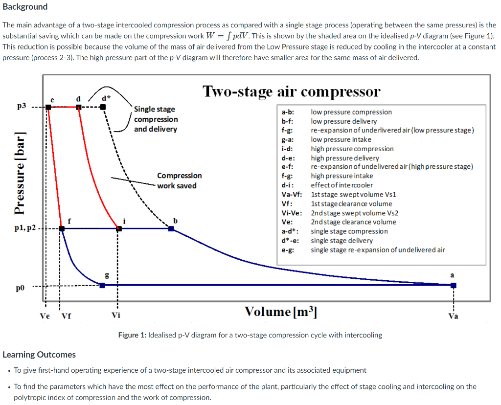
Background The main advantage of a two-stage | Chegg.com

The Limitations of Single Stage Air Compressors. - Bright Hub Engineering

A two-stage air compressor operates at steady state, compression 10m/min of  air from 100 kPa and 300K to 1200 kPa. An intercooler between the two stage  cools the air to 300K at
A two-stage air compressor operates at steady state, compression 10m/min of air from 100 kPa and 300K to 1200 kPa. An intercooler between the two stage cools the air to 300K at

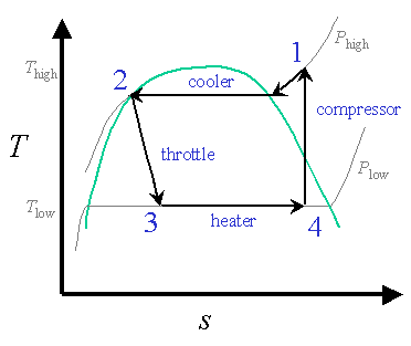
Design of Vapor-Compression Refrigeration Cycles

Module 5 - PV diagram of Multistage reciprocating air compressor with  intercooler & workdone - YouTube
Module 5 - PV diagram of Multistage reciprocating air compressor with intercooler & workdone - YouTube

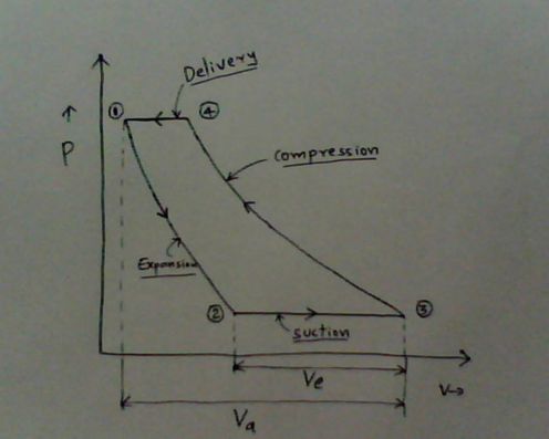
Single Stage Air Compressor Basic Theory With PV Diagram Explanation

Vane Compressor or Blower - Diagram, Working, Advantages, Disadvantages

File:Working of axial compressors and their P-V and T-S diagrams.jpg -  Wikimedia Commons
File:Working of axial compressors and their P-V and T-S diagrams.jpg - Wikimedia Commons

The compressor indicator diagram - YouTube

Solved Referring to the diagram below, a single | Chegg.com

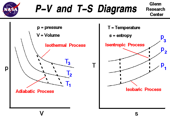
P-V and T-S Diagrams

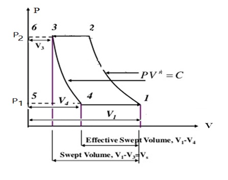
Explain working of single stage reciprocating compressor with P-V diagram.

2 Reciprocating Air Compressors (Working and p-v diagram) - YouTube

Applied Thermodynamics Module 6: Reciprocating Compressor

Thermodynamics: Lesson 31. AIR COMPRESSORS

Work Done By Reciprocating Compressor without Clearance Volume (Single  Stage, Single Acting) With PV and TS Diagram | Mecholic
Work Done By Reciprocating Compressor without Clearance Volume (Single Stage, Single Acting) With PV and TS Diagram | Mecholic

THERMAL SYSTEMS SMEX1044 UNIT II: AIR COMPRESSORS